
Capacitive displacement sensor C900
The C900 is an ultra-high precision capacitive displacement sensor with nanometer resolution.
It is a non-contact displacement measurement instrument based on capacitance, with high resolution, excellent accuracy, stability and reproducibility, providing a perfect solution for many impossible measurement applications. Its fast response time and extremely low noise level make it an ideal choice for critical measurements of rotating spindles and shafts, discs, tires, and wafers.
| Characteristic : | Application : |
| Non-contact, non-destructive measurementReal-time process measurement up to 5 kHzUsing a passive capacitance probe to achieve excellent temperature stability | Displacement, thickness, sizeAxial runout, vibrationFlatness or profile, internal/external diameter |
Controllers
- Controller C900
Controller C900: The standard version of the controller C900, as shown in Figure 1, is installed in an aluminum alloy box, which has good anti-interference performance. The front panel has two SMA connectors for connecting sensor probes and output signals, and the back panel has an I / O port, which is a 9-pin connector.


Fig.1, Sensor C900

Fig.2, Controller C900 drawings
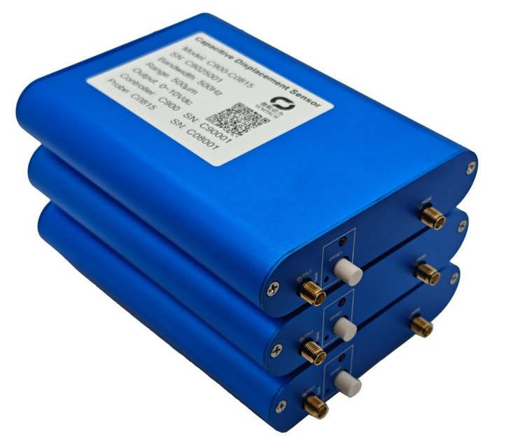
Fig.3, Physical diagram of controller C900
Sensor Probe
Sensor probe: There are currently three types of probes, all with a range of 0.5 ~ 2mm, with different structures. The standard version C0815 is usually in stock, while the other two probes may need to be produced after placing an order. The default cable length is 2m, and all connectors are SMA male connectors. Customization is also available upon request.
Table 1, Probe parameters

Order example
| C900-C0815 |
| ① ② |
① Controller model, standard version C900;
② The probe model is shown in Table 1. The probe cable length is 2m by default..
Use of probe range
It is recommended to use 10% to 90% of the full scale, as shown in the Figure 4.

Fig.4, Probe range
Installation and usage
1. Probe connection
The SMA female connector on the front panel of the controller C900 is labeled Probe and is used to connect the sensor probe, which has an SMA male connector on it. Please pay special attention that the probe shell has a voltage of about 2V, so the probe shell must be grounded or connected to the GND of the power supply using a wire, as shown in Figure 3.
2. Power supply and output I/O
The I/O ports are located on the back panel of the controller C900, marked Power & Output, for power supply and output.
The power supply requirement is ±15Vdc (error ±0.5V dc), the power supply noise is less than 0.01V dc p-p, and the current is not less than 300mA.
3. Output
The output signal is an analog voltage of 0 ~ 10Vdc, which can be connected to the SMA connector marked as Output on the front panel of the controller or the output on the back panel I/O port, and can be used to connect a digital multimeter or a data acquisition card.
4. About Offset
The front panel offset switch is used to adjust the bias to achieve a voltage output of -5V ~ 5V. Under normal conditions, it is in a pop-out state. If needed, press the offset switch. At this time, the front panel LED light is on. Use a screwdriver to rotate the knob under the left of the offset switch to adjust the output voltage. In the output bias state, the offset switch needs to be kept open.

Fig.5, Wiring diagram