
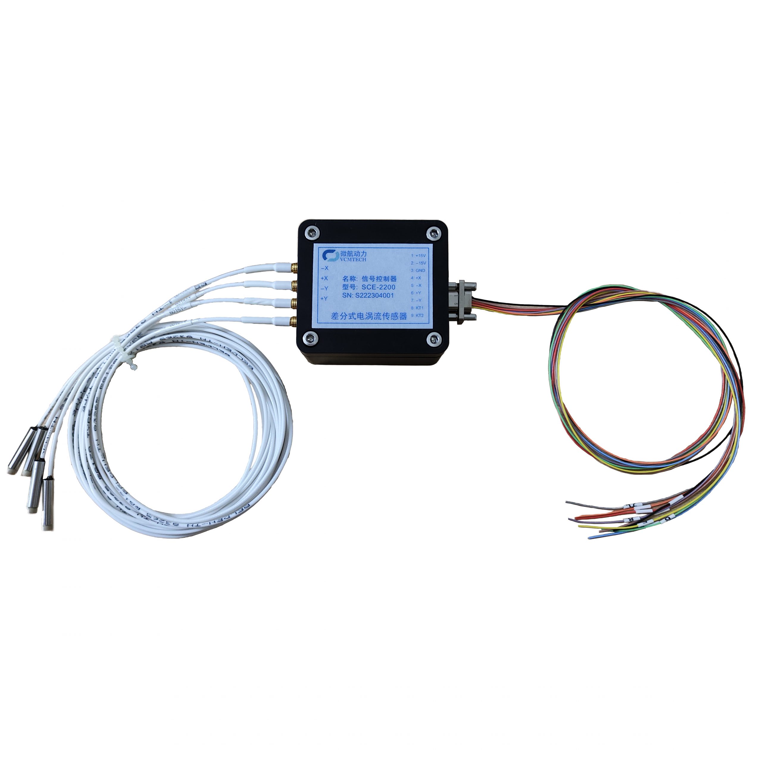
Fast steering mirrors (FSMs) require rapid, repeatable angular positioning for beam stabilization, tracking, image stabilization and line-of-sight control. The SCE-2200 differential eddy current sensing system provides non-contact displacement feedback with a default 20 kHz frequency response, making it a practical feedback option for compact, high-dynamic mirror mechanisms.

Why Position Feedback Matters in an FSM
An FSM typically combines a lightweight mirror, flexure or pivot structure, voice-coil actuators and a closed-loop controller. The controller must know the mirror position with low delay so it can correct disturbances and accurately follow the commanded angle. Open-loop actuator current alone cannot compensate for structural tolerances, external vibration, temperature drift or load variation.
A differential eddy current sensor measures the change in gap between its probes and conductive targets without physical contact. In an FSM, the probes can be arranged around the moving mirror carrier so that mirror rotation produces opposite gap changes. Subtracting the paired signals increases sensitivity to angular motion while rejecting common-mode translation and part of the environmental drift.
How the SCE-2200 Fits the Feedback Loop
- Mirror motion: voice-coil actuators rotate the mirror around one or two axes.
- Differential gap sensing: opposed probes measure the relative change between the mirror carrier and the fixed sensor frame.
- Signal conditioning: the SCE-2200 controller converts the probe signals into a low-impedance ±10 V analog output.
- Closed-loop control: an ADC or servo controller reads the analog feedback and adjusts actuator current to minimize position error.

Key SCE-2200 Parameters for FSM Design
| Parameter | SCE-2200 value | Relevance to FSM feedback |
|---|---|---|
| Measurement range | ±0.25, ±0.50 or ±0.90 mm | Select according to the probe radius and maximum mirror angle. |
| Analog output | ±10 V | Compatible with common servo controllers and data-acquisition hardware. |
| Typical sensitivity | 20 mV/μm | Provides a strong analog signal for small displacement changes. |
| Non-linearity | <0.5% FSO | Supports predictable position calibration across the selected range. |
| Resolution at null | <0.004% FSO p-p at 1 kHz | Useful for detecting small motion near the centered mirror position. |
| Frequency response | 20 kHz default | Supports high-bandwidth sensing in fast control loops. |
| Thermal stability at null | <0.005% FSO/°C | Helps reduce zero-position drift with temperature. |
| Input supply | ±15 V at 53 mA | Standard bipolar supply for integration into the electronics enclosure. |
| Operating temperature | −40°C to 80°C | Suitable for a wide range of industrial and optical environments. |
| Dual-channel power dissipation | <1 W | Limits the sensor electronics’ thermal impact near the mirror assembly. |
Recommended Mechanical Arrangement
For one-axis feedback, a common approach uses an opposed probe pair positioned at equal radii from the mirror pivot. For two-axis FSMs, a second orthogonal pair can be added. The final probe count and placement depend on the flexure, available space, target geometry and required rejection of translation. The sensing targets must be electrically conductive and should provide sufficient area throughout the full angular travel.

Integration Guidelines
- Choose the operating range first. Convert the maximum mirror angle into displacement at the probe radius, then retain margin for assembly tolerance and shock travel.
- Set the nominal gap near the electrical null. Available null gaps include 0.4, 0.65 and 1.0 mm, depending on the selected configuration.
- Keep the geometry symmetric. Equal probe radii and target conditions improve differential cancellation and simplify angle calibration.
- Protect the analog path. Route probe and output cables away from actuator power wiring, switching amplifiers and other high-current conductors.
- Calibrate the complete mechanism. Determine volts-per-degree after final assembly because probe radius, target angle and mechanical stack-up affect the conversion.
- Match the control bandwidth. The 20 kHz sensor response is only one part of the loop; the ADC, controller, actuator and mirror mechanics must also support the intended bandwidth and phase margin.
Example Closed-Loop Signal Chain
FSM command → servo controller → voice-coil actuator → mirror motion → differential SCE probes → SCE-2200 controller → ±10 V feedback → ADC / servo controller
The SCE-2200 supplies position feedback; actuator sizing, loop compensation and final system performance remain dependent on the complete FSM design.
Conclusion
By combining non-contact differential measurement, a 20 kHz default frequency response and ±10 V analog output, the SCE-2200 can provide precise mirror-position feedback without adding friction or contact force to the mechanism. Correct probe geometry, gap selection, cable routing and system-level calibration are essential to achieving reliable closed-loop FSM performance.